After creating my first timelapse with a digital SLR and a TI-89 programmable calculator, I was hooked. However, I felt that my timelapses were lacking something. Many professionally-made timelapses include some sort of ultra slow pan, zoom, or other frame motions in addition to the motion being timelapsed. I figured it shouldn't be too hard to make a device that would move my camera really slowly, so I started designing this system. I had a full CAD model of the panning platform before I even started building, so everything came together pretty smoothly.
The platform is driven by two stepper motors (the same motors used by the Makerbot Cupcake CNC, in fact) and is controlled with an Arduino board. The firmware allows for microstepping of the motors which, combined with the drive ratios used, can provide snail-paced motion of the camera. The system can also move a camera fairly fast, though I haven't come up with a use for that operation mode yet. The panning rig can move on two axes: left-right (pan/yaw) and up-down (tilt/pitch).
Making the Frame

I created the frame of the panning platform from 3/16 inch aluminum plate. I wanted to keep the whole thing as light as possible, and I felt that 1/4 inch aluminum was overkill. I also designed the geometry of the parts to be lights; I eliminated material wherever possible. The panning platform was designed to be fabricated on a water jet cutter so all the frame pieces are planar. Most of the critical holes were cut undersize so that they could be drilled out to exact dimensions later.
I was also sure to make the horizontal pieces (3 large rectangular pieces shown at right) a little longer than they needed to be. Since there were going to be pieces of the frame bolted to the ends of the three horizonal plates, those three plates needed to have very square ends. Water jet cutters leave a slight draft angle on the cut edges, so the raw cut edge wouldn't provide a square surface to bolt onto. Therefore, I used a milling machine to clean up the short edges and prepare them for bolt holes.
I drilled and tapped three bolt holes on the short edges of all three horizontal plates. These holes would be used to mount the vertical portions of the frame. I then used a reamer to ream out the critical holes so that the axis bearings could be press-fit in. Holes for press-fit bearings must be designed very carefully--too big and the bearing will fall out, too small and the bearing will bind. Reamers allow for hole diameter enlargements in steps of 0.001" or less.


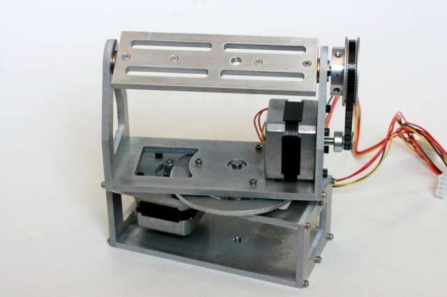
Adding Motion
Once the frame was built, I had to add components to make the thing move! There are two independent drivetrains. Both axes are geared down to make them slower, since slow, steady motion is the goal. The up-down motion is controlled with a timing belt and pulley pair while the left-right motion is controlled with a pair of gears. I chose this configuration because I wanted a gear ratio as large as possible for panning while using only two gears. This meant I needed a driving gear as small as possible and a driven gear as large as possible. Pulleys require some space between them while gears intermesh. This means that in the given design envelope, a driven pulley would have to be smaller than a driven gear--non ideal for getting a large gear ratio.

The pan axis was not too complex. I designed a short axle that would hold the large gear, which is in turn attached to the top half of the system. There is a needle roller thrust bearing that the gear and top half sit on. This provides very smooth motion with no binding. The most difficult fabrication step for the pan axis was making a bolt pattern on the face of the gear. It would have been difficult to clamp the gear in a mill without damaging the teeth, so I decided to hand-hold the gear and drill the hole pattern with a drill press. In order to get the placement right, I lasercut a circular jig that fit tightly over the gear hub. The jig had three holes in the proper place for mounting the gear to the top half of the system.

It was a bit more difficult to fabricate the tilt axis. I designed a plate that my camera can attach to, and that plate needed to be rigidly fixed to the tilt axle. I decided the best way to do this was to put some flats on an axle for the camera plate. I also had to split the axle into two halves, since I needed to be able to access the bottom of the camera plate when connecting and removing the camera from the rig. To make the tilt axles, I started with some oversize round steel stock. I turned it down to the correct diameter, using sandpaper towards the end to get the diameter to within about +/- 0.001" of the required diameter. It was necessary to keep such a tight tolerance since the bearings needed to just slide on the axles with very little play. Then I put the axles in a collet block on the milling machine to mill the flats and drill the bolt holes.
I attached the tilt axles to the camera plate along with some solid brass thrust bearings. This allowed for smooth tilting camera motion without the camera plate binding on the frame. I had to use flathead screws to attach the camera plate to the tilt axles because the top of the plate had to be smooth for the camera to sit on.


Putting It All Together
After fabricating the frame and motion components, all that was left was to assemble the system. This part was fairly straightforward (and exciting!) The motors were attached to the frame, bearings were press-fit into holes, and pulleys/gears were attached to their axles with set screws. Everything went together quite well. Of course, the mechanical system can't do too much without control and drive circuitry--that part is coming soon!


It Works!
This is one of the first videos I made with the timelapse panning platform.
I got all set up with a semi-mobile system and did an outdoor timelapse. Here is a scenic timelapse taken in Fairbanks, Alaska during the summertime.