Making the Solar Panel


I recently came upon a vast supply of small solar panels via MIT reuse--an email-based service to reuse unwanted stuff. I knew this particular post was a goldmine as soon as I saw all those solar panels, so I quickly snatched them all up, wondering what I could possibly do with such a hoarde of solar cells. The first step was to remove the solar cells from their perf boards and desolder any wires attached to them. Whatever past project these were used in obviously required three cells to be wired in parallel with a rather large (4700 uF) capacitor on a perf board. Hey--free capacitors, too! I harvested all I could from the boards, and I was ready to go. There were 13 of these board assemblies, for a total of 39 solar cells and 13 capacitors (not to mention the 13 perf boards themselves).

The cells themselves are about 2.25 inches square, and have 'PCB-60608B' written on the back of them. Strangely, even though each solar panel was labeled with the same number, there was quite a variety of differing panel styles. Anyways, I couldn't find much on the 'PCB-60608B' solar cells, but I did find what appears to be a schematic of the solar-powered accent lights these panels were made for. I started doing some tests with the cells to see what sort of power they could produce. They actually did pretty well, even under a simple table lamp. Anxious to try them out on the sun, but with the sun long past the horizon, I had to make do with halogen lights. It appeared that one cell was able to put out around 3 volts under the light of my desk lamp. Good! I wired three of them together in series and sure enough, I got an output near 9 volts. It was exciting to verify that the cells were in working order, and indeed put out a relatively high voltage. I measured the short-circuit current of one cell under the desk lamp, and (as I expected) it was quite low--around 10 mA. Surely, under sunlight, there would be a higher power output. Also, I'm able to wire the cells in parallel to increase the maximum current output of the solar panel--voltages add when cells are in series, and currents add when they are in parallel.
I went about constructing such a panel. I wired eight cells in series pairs to get four 6 volt panels. Then, I wired these in parallel so that I got some sort of usable current out of the 8-cell solar panel. I figured I would want to charge USB devices, so I dug up a 7805 5V linear voltage regulator to bring the 6 volt output down to 5 volts. After hooking up an old USB port, I was able to test the charging capabilities of my newly-built solar panel. It worked! My iPod successfully went into "charge mode" upon connecting it to the panel and turning on the desklamp.
Once I understood the cells' output, I made a nice 16-cell panel for charging my devices. They are wired in pairs so that the output is around 6 volts, and with 8 of these pairs wired in parallel, the current output should be acceptable. If the current output of a solar panel is too low, the device may charge very slowly or even lose charge. If the charger is supplying less power than the cell phone uses by simply being on, then it will lose power, even though it may tell you that it is charging.


Designing the Charging Circuit
Solar cells are quite inefficient at converting light into electricity. That meant I wanted to be as efficient as possible when charging my USB devices. Unfortunately, the 7805 linear voltage regulator (as pictured above) is very inefficient. The voltage regulator takes a variable voltage input (above 5V) and outputs a relatively steady 5 volts. It works by simply burning off the extra energy as heat, which doesn't make much sense for a solar charger. So, I looked into a DC/DC converter, which is really just a transformer. It takes a higher voltage input, and puts out power that is at a lower voltage, but carries more current. Ideally power (power = voltage*current) would be conserved, but in reality, DC/DC converters are around 70-80% efficient.
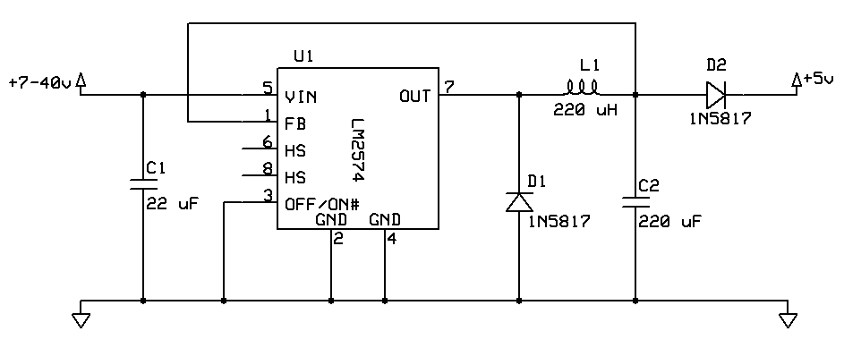
I learned about DC/DC converters from Ladyada, though the one used there is a "boost" converter (it increases voltage), while I wanted to use a "buck" converter to decrease the voltage from 6V to 5V. I found a DC/DC buck converter rated for 500 mA (the USB limit) and with an output voltage of 5V (also based on USB specifications): the LM2574 chip. The datasheet for this chip is really helpful in designing a voltage regulation circuit, and I was able to simply follow the circuit schematic and design suggestions there. It doesn't require a whole lot to get the converter working--just a couple of passive components. Here's a schematic of the 5V DC/DC converter: (note: as of 5/1/2010, I removed a diode at the output of the converter [D2]. The diode was unnecessary and only introduced a voltage drop at the output. Here is the old schematic.)


I wired up the circuit on a piece of perf board and got it working just as I wanted. You can see the 8-pin voltage regulator chip at the top and the inductor in the lower right. You may have noticed an extra diode on the output. That's to keep the USB device's battery from trying to run current backwards through the DC/DC converter. As with most projects, they get a little better if you put them in a nice case. For this circuit, an Altoids tin was a bit too large, but Katie had a nice little Facebook mints tin from a career fair. It fit perfectly! I had to cut holes for the voltage input (a mono headphone-style jack) and the voltage output (a standard female USB connector). I also put some bits of rubber on the bottom to keep it from sliding around.
The finished 5V DC/DC buck converter to take the variable output from the solar panel and reduce it to 5V for charging USB things:


Using a Battery
The problem with just a solar cell to charge things is that you can only charge a device when the sun is shining. If you want to charge something at night, there's no way to make use of all the sun's energy that was hitting the solar panel during the day--there's a lot of wasted power unless you're very careful about when you charge. A much more convenient (and sensible) method is to use some sort of battery to store the solar energy that you don't immediately use.
After a lot of experimentation, I settled on a 6 volt, 5 amp-hour sealed lead acid battery. The short version is that this means when the battery is full, it is storing more than enough energy to fully charge my cell phone. Here's the long version: The number of amp-hours (Ah) is a measure of battery capacity, which is the amount of energy stored. A battery with a capacity of 5Ah can supply (in theory) 5 amps for one hour before being "dead". At a nominal voltage of 6V, a 5A current means a power output of (6V * 5A) = 30 watts, which is 30 joules/second. Since there are 3600 seconds in an hour, my 6V, 5Ah battery can hold (30 joules/second * 3600 seconds) = 108,000 joules of energy. My cell phone battery, on the other hand, has a battery that is 3.7V and 930mAh, which corresponds to an energy capacity of (3.7V * 0.930A * 3600s) = 12,388 joules of energy. Most portable device batteries (like an iPod) are similar to the cell phone's, so the estimation still holds.
There are many, many intricasies to charging batteries, but I went a pretty simple route that seems to work fine. I am holding a constant charging voltage on my battery of 6.8 V. This is the recommended charging voltage for something like a solar charger application where the battery is usually fully charged and is not deep-cycled (used up all the way, then recharged, then used up all the way, etc). I chose to use a Zener diode to keep the solar panel output limited to 6.8 V so as to not overcharge the battery. I found a useful website about Zener diode voltage regulators that goes over the basics of using Zener diodes for exactly my application. Basically, a Zener diode has a very specific breakdown voltage. Above this breakdown voltage, it actually conducts current in the reverse direction, so it can protect the battery from voltages higher than the breakdown voltage by being placed backwards in parallel with the battery. The diode and resistor have to be rated at a relatively high wattage (2W) because any extra power from the solar cell (i.e. when the battery is full) will be burned off through those components as heat. After making the battery charging circuit, I had a complete solar charging station! I also had to add a diode between the panel and the battery to keep the battery from discharging across the panel at night. Here's a circuit schematic of the complete system:

So, in summary, I made a 16-cell solar panel to provide 7-9 volts at around 200 mA of current on a clear day. This power goes to a 6V lead acid battery in parallel with the panel, which is protected from overcharging by a 6.8V Zener diode. The power produced by the cell and that stored in the battery is fed through a DC/DC buck converter to bring the output down to 5V. That 5V output is in the form of a USB plug for charging my mobile phone or iPod.


The panels pictured above are simply leaned on some wooden blocks to keep them steady. This solution is not ideal for a number of reasons. first, the angle of the panels can't be changed. The sun's angle changes with the seasons: higher in the summer, lower in the winter. Without an easy way to change the panels' angle, I can't capture all the available solar energy and maximize panel efficiency. Also, it is not a robust design, and the panels often fall over in the wind. With those two design points in mind, I created an aluminum housing for my panel. The angle can be changed easily via a mechanism not unlike those found in adjustable lounge chairs. The housing was made from scrap parts I found around the MIT Edgerton Center.


