Arduino source
While working on another project, I found the need to connect an Arduino to my Android phone for data collection. I found a fantastic library written by Mike Wakerly for connecting Arduino (and other USB to serial devices) to an Android app.
A few copy-and-pastes later, I had a working serial connection between my phone (Galaxy Nexus running 4.2.2) and microcontroller. The possiblities were endless! I recently got a 5m RGB LED strip, and Katie Dektar recently finished a fun Android app called Color Namer. Well, when she open-sourced Color Namer, my mission was clear: use my phone to control five brilliant meters of multicolor LEDs.
Connect Android to Arduino
With names so similar, it is no surprise that Android and Arduino play nice together. Mike's library makes the connection painless. Take a look at his short how-to for the basics and his example Java code for more info. For this project, I only needed to write serial data to the Arduino, not read. This made the code a bit simpler, as I didn't need a serial data listener on the app. Here are some snippets from my code:
//set up the serial device

public class MainActivity {
    private UsbManager usbManager;
    private UsbSerialDriver device;

    @Override
    protected void onCreate(Bundle savedInstanceState) {
    // Get UsbManager from Android.
    usbManager = (UsbManager) getSystemService(Context.USB_SERVICE);
    }

    @Override
    protected void onPause() {
        super.onPause();
        if (device != null) {
            try {
                device.close();
            } catch (IOException e) {
                // Ignore.
            }
            device = null;
        }
    }

    @Override
    protected void onResume() {
        super.onResume();
        device = UsbSerialProber.acquire(usbManager);
        Log.d(TAG, "Resumed, mSerialDevice=" + device);
        if (device == null) {
            Log.d(TAG, "No serial device.");
        } else {
            try {
                device.open();
                Log.d(TAG, "serial device opened");
                device.setBaudRate(115200);
            } catch (IOException e) {
                Log.e(TAG, "Error setting up device: " + e.getMessage(), e);
                try {
                  device.close();
                } catch (IOException e2) {
                    // Ignore.
                }
                device = null;
                return;
            }
        }
    }
  //write the serial data

  private void updateTextAreas(int col) {
  byte[] colorBytes = {(byte)Color.red(col),
                       (byte)Color.green(col),
                       (byte)Color.blue(col),
                       0x0A};
  //remove spurious line endings so the serial device doesn't get confused
  for (int i=0; i<colorBytes.length-1; i++){
    if (colorBytes[i] == 0x0A){
      colorBytes[i] = 0x0B;
    }
  }
  //send the color to the serial device
  if (device != null){
    try{
      device.write(colorBytes, 500);
    }
    catch (IOException e){
      Log.e(TAG, "couldn't write color bytes to serial device");
    }
  }
}
I also wrote a small Arduino sketch to recieve the color data and control the RGB LEDs. (Download sketch) It was a pretty easy task with the Arduino Serial library:
//pin definitions
const int red = 11;
const int green = 9;
const int blue = 10;

//maximum duty cycle to be used on each led (for color balancing)
const int max_red = 255;
const int max_green = 90;
const int max_blue = 100;

byte colors[3] = {0, 0, 0};
byte lineEnding = 0x0A;

void setup(){
  pinMode(red, OUTPUT);
  pinMode(green, OUTPUT);
  pinMode(blue, OUTPUT);

  Serial.begin(115200);
}

void loop(){
  if (Serial.available() > 2){
     int bytesRead = Serial.readBytesUntil(lineEnding, (char*)colors, 3);
  }
  analogWrite(red, map(colors[0], 0, 255, 0, max_red));
  analogWrite(green, map(colors[1], 0, 255, 0, max_green));
  analogWrite(blue, map(colors[2], 0, 255, 0, max_blue));
}
To make the physical connection between Arduino and Android, I needed a USB On-The-Go (OTG) cable. Since I didn't have one and Fry's was closed, I made one from two old USB cables. You simply short pin 4 to pin 5 (GND) on the micro USB connector and then replace the male USB A end with a female USB A connector. There is a nice tutorial over on the xda forums


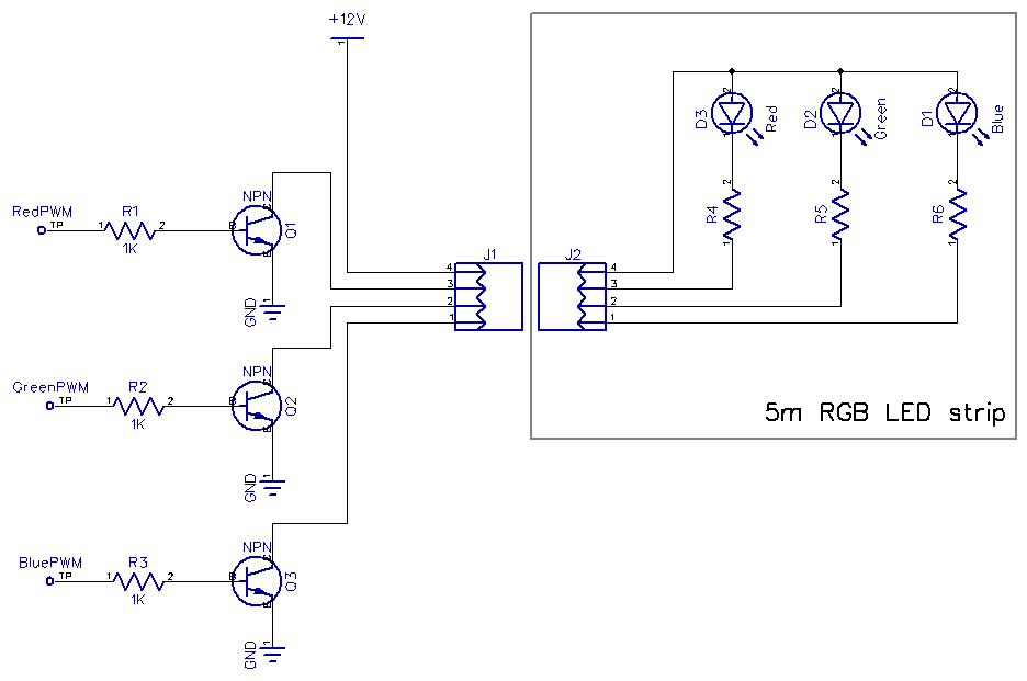
Build the Circuit
The LED strip has probably about a million LEDs in parallel, so each color can draw up to about 1.5A at full brightness. The poor Arduino would try its best, but those digital I/O pins simply can't output that kind of power. With a transistor, the signal from the Arduino's I/O pins can be used to switch the much higher current required to drive the LED strip. Three NPN transistors and a 12V power supply later, I had a simple LED driver circuit. The 1K resistors connected to the base of the transistors are there to limit the current going into the base. Ususally this would be higher (~10K) but I was overdriving my little transistors: they are rated for 0.1A, and I was passing 1A through them... If you give this a try, I recommend getting higher power transistors rated for at least 2A.
Put it All Together
Here are some images of the project. You can see the three transistors on the breadboard with the LED strip running off to the left. I used a short ribbon cable to connect the Arduino to the transistors. The USB cable coming from the Arduino goes straight to the OTG cable connected to my Android phone.


